No point putting in a new engine with an old turbo that's been beaten on just so the turbo can leak oil all over because the bearings are shot, when a full rebuild kit can be had for $120 shipped to Canada from
G-Pop Shop. This series will cover disassembling and reassembling a turbo, and show you just how easy it is.
Okay, maybe it's not that easy, at least not the disassembly part. Think about it -- these turbos are 20 years old and have been subjected to exhaust heat, and their own heat generated from spinning amazingly high RPM.

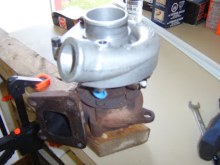
First, a shot of our victim: A Garrett T03, in this configuration known as the "Turbo II" turbo. The stock Mitsubishi TEO4H is on the right... you can see why the Garrett is a better choice for performance. Sure, a larger turbo will take longer to spool up, but when it does, hang on to your pants.
The first step was to remove the "swingvalve", which includes the exhaust outlet. This Garrett has the larger 2 1/2 inch exhaust opening, instead of the 2 1/4 inch opening in older models. There are 5 bolts holding the swingvalve to the turbine housing, one is hidden inside the swingvalve. I lucked out and all came out with a little penetrating oil. The general consensus seems to be that you require heat to get the bolts out without snapping them off.

After removing the swingvalve and realizing I had no vise to mount the turbo in, I bolted it to a 2x4 which I could clamp down to the workbench through 3 of the swingvalve holes. This is where the fun begins. There are 6 bolts that hold the centre cartridge (including the shaft and bearings) to the turbine housing. These are usually the worst bolts to remove, and clearance is quite limited. I managed to get a thin box-end wrench on 3 of them, the other 3 need an open-end wrench. I soaked the bolts in penetrating oil for quite a long time. I sprayed them daily for several weeks, because again the general consensus is that heat is required for all 6 bolts, and that the housing needs to be heated cherry-red before you can even think about removing them. That cuts out your garden variety propane torch as a source of heat.
Somehow I again lucked out and 5 of the 6 bolts came out without problem, and without heat. Wouldn't you know it, though, that the one bolt that had to be stubborn was one of the ones that needed an open-end wrench. A little heat helped break it free, but nowhere near the amount of heat to turn the housing any colours.

With the bolts loose, the next step is to separate the centre cartridge from the turbine housing, usually 2 of the bolts line up on the coolant fitting bosses, and you can turn these bolts out a little at a time to press the halves apart. For some reason mine came apart on one side before the other. A couple of quick taps on the oil drain boss popped the other side out and separated the halves. In this photo I had already removed the compressor housing, which is held on by 6 bolts, and comes off with relative ease.
Care must be taken during this step to ensure you separate the center cartridge from the turbine housing evenly so you don't bind the wheels in the housings, potentially damaging the wheels, in which case you just made yourself a paperweight.

With the center cartridge out, the next step will be to make some index marks on the wheels so you can reassemble it the same way it came apart to preserve balance. I've seen mixed reviews online as to whether the wheels were balanced individually or as a unit from the factory, or even if balance will have an effect on performance. Best to play it safe here. You need a 12 point socket or box-end wrench on the compressor nut, and a 6-point socket on the turbine end of the shaft. Remove the nut, and the compressor wheel should slide off. The shaft and turbine wheel might be trying really hard to stay in the cartridge, this is likely because of the "piston ring" in the exhaust end is acting as a bit of a retaining clip. Just press on the shaft and it'll pop out.
The shaft is likely to be grimy. I used a scotchbrite pad and some acetone to clean mine up. Inspect the shaft to make sure that it doesn't have ridges or grooves from the bearing surfaces. Normally the bearings should take all the wear, and in my case, they did. With the shaft and wheels out of the way, you can now remove the compressor backing plate, which is held on by 4 small bolts. Don't let their size fool you -- mine were in TIGHT with red thread locker, so it took a bit of effort to remove them.

With the backing plate off, you can see the thrust bearing and the oil seal. In my case I didn't have any thrust play but I'm replacing the thrust parts anyway.
I'm currently waiting for my rebuild kit to arrive, according to the tracking number provided by G-Pop Shop it should be here any day.